The TASS switch system made a design compromise that means its RF performance has some variation depending on which combination of ports is selected. When using a port that’s not at the far end of the board from the common, there is a transmission line stub of varying length that affects VHF performance. A single TASS board works well through 150 MHz. The question has been what happens when you build a multi-board system? Now that I have the TASS multiplexer system assembled, I can do that test.
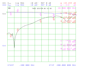
First, here is the best possible configuration: port 8 of board B, which feeds all the way through boards A and B, and then through coax to board D, feeding port 8 at the far end of that board, meaning that there are no stub sections:
This shows very nice performance to at least 100 MHz.
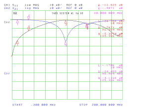
Now, here’s the other extreme — port A1 to port D5:
In this case the signal path has two stubs: one about 10 inches long (3 inches of PCB microstrip on each board, plus a coax jumper about four inches long), forming a 10 inch stub, and another made of the 3 inch microstrip on board “D”. You can see the effect.
This worst-case configuration is usable through about 40 MHz (where the SWR is 2:1 and insertion loss a bit over 0.5dB), and completely falls apart a bit below 60 MHz. What’s more important is that depending on the port selected, you may get either the great, not-so-great, or somewhere-in-between response. In my application measuring pulse-per-second signals, the variation won’t have a material effect,* but the multi-board TASS system won’t be at its best if the goal is precision RF measurements, particularly above 30 MHz.
* The frequency response limitation will soften the rising edge of the PPS pulses, but not to the extent that noticeable accuracy is lost.


