I’ve been looking for an antenna switching solution to use in my new ham station. I have several antennas for HF and 6M that all connect to the same amplifier in the shack, which has only a single output connector. A remote switch at the tower (about 20 feet from where the cables enter the house) seemed like a good idea. In looking around, I found several commercial units, but they had one or more disadvantages; they were either (a) expensive; (b) not spec’d for 6M; (c) questionable power handling; or (d) using UHF connectors (I’ve standardized on N connectors in my system).
There are a number of Eastern European hams who sell nifty kits on eBay for very reasonable prices. Several of them have remote coax switch kits. I finally decided on the YU7WW 6-position switch currently available on eBay for $49.95.
I liked this design because Mirko has laid out a nice, compact board that he says will handle 2KW and will go to 6M. His kit has a couple of features that were lacking in other kits I looked at — the RF paths are kept very short, he has good spike protection on the relays, and he uses a piece of PTFE teflon insulation between the board and the ground plane to protect against arcs jumping from the metal panel hardware to the signal conductors at high power. Another nice thing (though not unique to YU7WW) is that the relays are configured to short all unused antennas to ground.
The kit includes the PCB, PTFE insulation sheet, six nice quality relays, and bypass caps, etc. The interconnect is very simple — just put 12V on the wire for the relay you want to activate.
However, the kit does not include the RF connectors or a metal plate to mount them on. That means this is a bit of a DYI project.
Construction
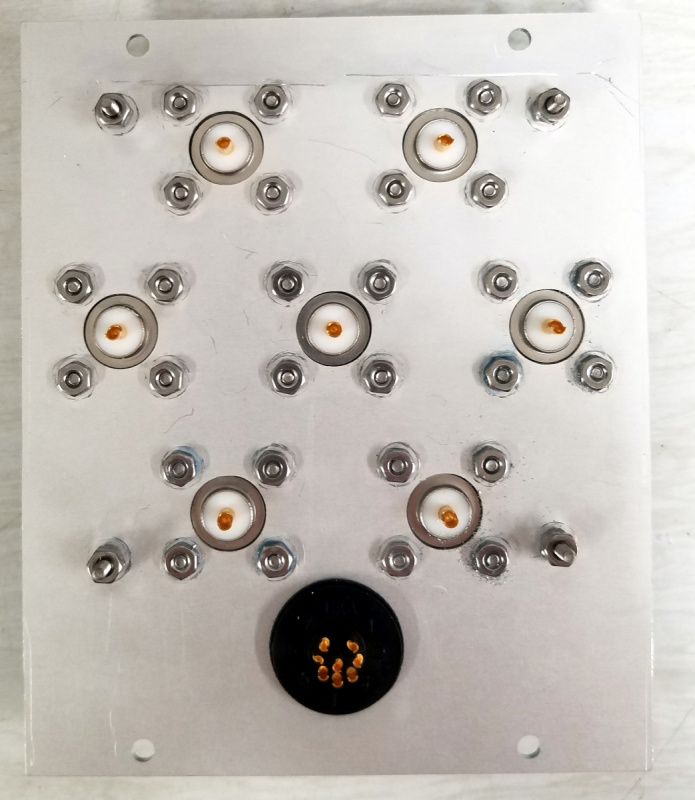
The first step was to come up with a panel on which to mount the coax connectors. I decided to use Front Panel Express for that; their free design tool makes it a snap to lay out flat metal pieces with milled holes and nice engraving.
The layout work was a bit challenging because, although the PCB is very nicely done, it’s not quite symmetrical and the connectors don’t line up on a neat grid. So I had to measure all the hole positions individually. It ended up working fine, though I might have a couple of the corner holes a millimeter or so off. If you’d like the Front Panel Express design file to use yourself, just drop me a line.
In addition to the panel, a few other parts were needed:
- 7 type N flange connectors; I found nice ones for $5 each on eBay.
- Connector for the control cable. I used a Connexall/Switchcraft 4282-8SG-300 8 position waterproof connector (Digikey part number SC1243-ND, cost $11.46). The matching cable end is Connexall 3282-8PG-3DC, Digikey part number SC1226-ND, cost $14.14. These connectors aren’t cheap, but they are waterproof and very easy to use.
- Box on which to mount the connector panel. I used a Hammond 1415C (Digikey part number HM307-ND, cost $23.75. It’s about as small in width and length as will accommodate the switch board, but is quite a bit deeper than necessary.
With the custom panel costing about $55, the total cost was a bit under $200. Not cheap, but less than equivalent commercial units and better fitted for my needs.
Two comments about the construction:
(a) I had to trim the PTFE to exactly the size of the PCB in order to clear the control connector and the box lip.
(b) I wanted to keep the ground plane as far from the signal path as possible in order to avoid possible arcs. To do that I used 1/4 inch 4-40 screws and nuts to mount the connectors, and elected not to use washers, which was a Bad Thing (the washers and longer screws required would have resulted in the mounting hardware touching the PTFE). But I put a good coating of Loctite on the screws that will hopefully help keep them from loosening over time.
Here are some pictures of the assembly:
Performance
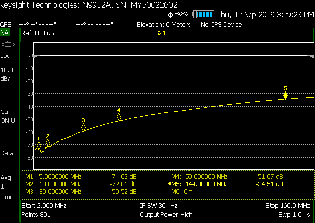
I haven’t put the switch into use yet, but I did do some measurements with a network analyzer. I swept from 2 MHz to 150 MHz (not really expecting decent performance above 6M). The results were pretty good, as shown in the plots below.
The insertion loss is very good through 6M — less than 0.3 dB — and the return loss (VSWR) is also very good at greater than 20 dB. The isolation is great at the lower bands. At 6M, 50 dB isolation is probably usable, but at 1 KW on 6M that means about 1 milliwatt of power will get through the unused switch ports. Assuming that the switch is used to route multiple antennas to one rig, rather than one antenna to multiple rigs, that shouldn’t pose any problems.
I think this switch is going to work very well for me, though the real smoke test of trying to run a KW on 6M through it is yet to come.


2 comments
Dear Mirko, I already bought from you the complete antenna switch kit, it works perfectly well until a ray burned two relays.
It was complicated to desolder the PCB from the RF connectors, there should be an easier way to replace the components.
Could you just send me the PCB or a new kit?
Looks like you don’t ship to Brazil anymore?
I make use of the OM3500HF amplifier.
Thank you very much 73 a great year 2022
Antonio PY2YW
Hi Antonio — I’m just a user of the kit and don’t have anything to do with sales or repairs. You need to get in touch with YU7WW for that.
73,
John